
So far, in this series, we have looked at how data is represented in binary, this included integer and boolean types, in Part I and then we followed up in Part II with floating-point numbers, which turned out to be quite the journey. In this part, we are going to look at binary logic and something readable.
I could go into the details of how to do binary math, but because there are better resources out there for this, I have decided not to go into it here.
However, because there are some basics I would like to touch on, I have included an overview of logic operations (gates) and now they loosely map to binary math. A good grasp of logical operations is important later on even in high-level languages.
Logic Operations
There are 6 logic operations or “gates” that are used in logic circuits.
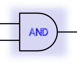
When both inputs are set to 1 the output is set to 1 otherwise 0
| Input A | Input B | Output |
|---|---|---|
| 0 | 0 | 0 |
| 0 | 1 | 0 |
| 1 | 0 | 0 |
| 1 | 1 | 1 |
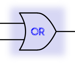
When one or both of the inputs are set to 1 the output is set to 1 otherwise 0
| Input A | Input B | Output |
|---|---|---|
| 0 | 0 | 0 |
| 0 | 1 | 1 |
| 1 | 0 | 1 |
| 1 | 1 | 1 |
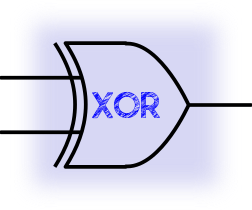
When one but not both of the inputs are set to 1 the output is set to 1 otherwise 0
| Input A | Input B | Output |
|---|---|---|
| 0 | 0 | 0 |
| 0 | 1 | 1 |
| 1 | 0 | 1 |
| 1 | 1 | 0 |

When both of the inputs are set to 0 the output is set to 1 otherwise 0
| Input A | Input B | Output |
|---|---|---|
| 0 | 0 | 1 |
| 0 | 1 | 0 |
| 1 | 0 | 0 |
| 1 | 1 | 0 |
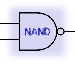
When both of the inputs are set to 1 the output is set to 0 otherwise 1
| Input A | Input B | Output |
|---|---|---|
| 0 | 0 | 1 |
| 0 | 1 | 1 |
| 1 | 0 | 1 |
| 1 | 1 | 0 |

Inverts the input 1 to 0, 0 to 1
| Input A | Output |
|---|---|
| 0 | 1 |
| 1 | 0 |
Everything is NAND
Now to go into the basic binary logic that underpins the operations above. You can, in fact, construct any binary operation by using just one or more NAND gates.
Basic Binary Multiplication
0 x 0 = 0
0 x 1 = 0
1 x 0 = 0
1 x 1 = 1
So this is an AND gate…
You can make an AND gate with two NAND gates by feeding the output of the first into both inputs of the second making it a NOT gate

0 NAND 0 = 1 NAND (1) = 0
0 NAND 1 = 1 NAND (1) = 0
1 NAND 0 = 1 NAND (1) = 0
1 NAND 1 = 0 NAND (0) = 1
With larger numbers, this works the same as decimal long division, and an explanation of how this works can be found here for Binary Multiplication, Binary Division
Basic Binary Add
0 + 0 = 00
1 + 0 = 01
0 + 1 = 01
1 + 1 = 10
So the LSB of the result is XOR of inputs and the MSB is the AND of the inputs and represents the carry.
Mor information on binary math can be found here for Binary Addition, Binary Subtraction
Four’d’NAND XOR
XOR in NAND gates is a bit more involved than the AND example above and uses 4 NAND gates.

| Input A | Input B | !(A • B) = C | !(A • C) = D | !(B • C) = E | !(D • E) = Q |
|---|---|---|---|---|---|
| 0 | 0 | 1 | 1 | 1 | 0 |
| 0 | 1 | 1 | 1 | 0 | 1 |
| 1 | 0 | 1 | 0 | 1 | 1 |
| 1 | 1 | 0 | 1 | 1 | 0 |
But like I said not going into the Math here just the gate basics and the construction of logic operations using NAND gates.
For more information on binary numbers and math see Wikipedia
Binary Coded Decimal (BCD)
There is also another standard used to represent decimal numbers in binary BCD, this format uses 4 bits to represent 1 decimal digit so 9 would be “1001” there are some cool clocks out there that show the time in BCD using a bar of 4 LEDs for each decimal digit
Some even drop the MSB of the four for the minutes and seconds 10s column as they will only ever go to 5 “0101”
H H : M M : S S
===============
0 0     0     0
0 0   0 1   0 0
1 1   1 0   1 0
0 0   1 1   0 0

22:35:20
This can be a useful way of encoding decimal numbers and was, maybe is, used in some storage of none integer decimal numbers for example using 40 bits to store up to a 39 digit decimal number using the first 4 bits as the location of the decimal point the remaining bits used to store BCD digits.
Chars and Strings
ASCII
American Standard Code for Information Interchange
This is probably the widest used and oldest of the standards for representing text and forms the basis for all the commonly used texts encodings like UTF8 and Windows-1250.
ASCII is a 7-bit encoding of 128 characters meaning the MSB could be used as a parity bit to insure integrity during communications. ASCII has undergone several revisions over the years. There are some features of ASCII that make its manipulation for programmers easier, Originally only uppercase with lowercase being added later, this was placed within a range that required only one bit to be flipped to change the case. Numbers are held sequentially with the last 4 bits representing their corresponding BCD value, making their translation to binary values simpler.
EBCDIC
Extended Binary-Coded Decimal Interchange Code
This is a standard introduced and used by IBM. EBCDIC is not readily used today, but there are a few systems out there that use it still. Further to this not being widely used, IBM created several incompatible versions of EBCDIC making it even harder to get systems to communicate data using it. From a programming perspective, this encoding is not particularly friendly as letters are not all consecutively located in the 8bit space and numbers, upper and lower case are stored in the reverse ordinal priority to ASCII making any ordinal based logic incompatible between the two encodings.
Strings
Strings are stored as a continuous list of consecutive characters using 0 (Zero or null) as an end marker, due to this exact size strings are immutable. This means that concatenation of two strings requires the allocation of new memory before then copying the two original strings into it. This method can result in your memory being littered with old strings that are not being used. That leads us to how to manage memory which is atopic for the next instalment…
Part IV !!